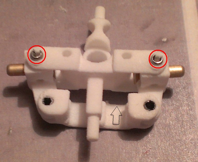
Want to get a chassis? Concerned how tricky it will be to build? It’s really not that difficult and it’s easier to build than the older ones, here’s how it’s done…
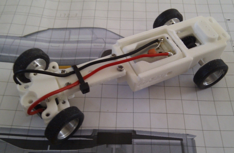
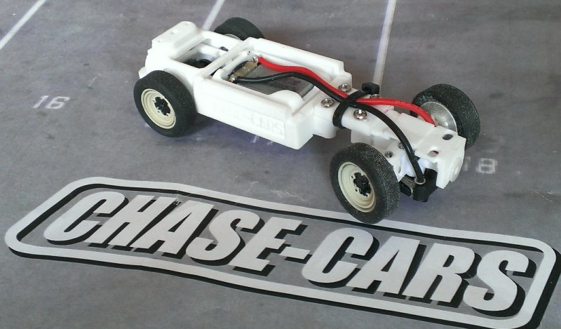
This is how the finished chassis will look, you can spin it around in your web browser
Just like the PCS32 Steering Unit, there are different widths available, specify which you need when you order:
27mm across front hubs – for narrow cars like the VW, Apollo, Skoda, or your own European car.
32mm across front hubs – for typical American cars, or most racing cars.
46mm across front hubs – for the Pickup Truck or your own scratchbuilt truck.
Tools you need are:
- 1mm drill bit
- 2.4mm drill bit. I use a Pin Vice with these, not a power drill, you just need to clear out some powder from the manufacturing process, not actually cut through plastic.
- Sharp knife
- Glue
- Small screwdrivers
- Small pliers
- Cutters
- 0.9mm Hex key for M2 screws
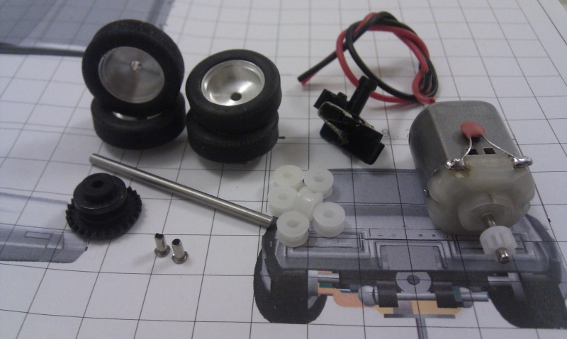
If you’re assembling the complete kit, all the components will be included. If you have the basic kit you will also need:
Mabuchi Motor 18.000rpm
Spur Gear (Black 36 tooth)
3/32 Stainless Steel Axle blank 45mm Long (or 35mm long for narrow cars)
6 Axle bearings white Nylon
Scalextric guide blade (long stem)
Alloy Wheel Hubs 15″ x 7″ to fit 3/32 axles
Tyres 20×07 Narrow Classics
First, go to your workbench. Is it neat and tidy? If not get a dustpan and brush, or in my case a shovel
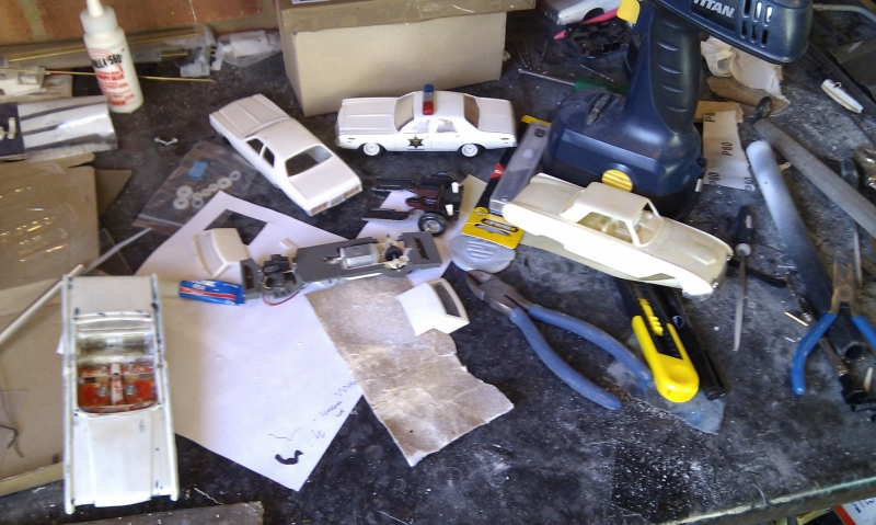
Well that’s a bit better. Tools a bit neater, and more importantly I’ve got The Rockford Files theme playing on my mp3 player, just to get me in the mood for some classic ’70s car chase action.
This is what the chassis looks like when it’s out of the box. All the parts are together, held by 1mm diameter “sprues”. They’re not really a sprue in terms of injection moulding, just a way of holding the parts together whilst it’s being sintered.
This has the 27mm (narrow) front end but they all assemble the same way.
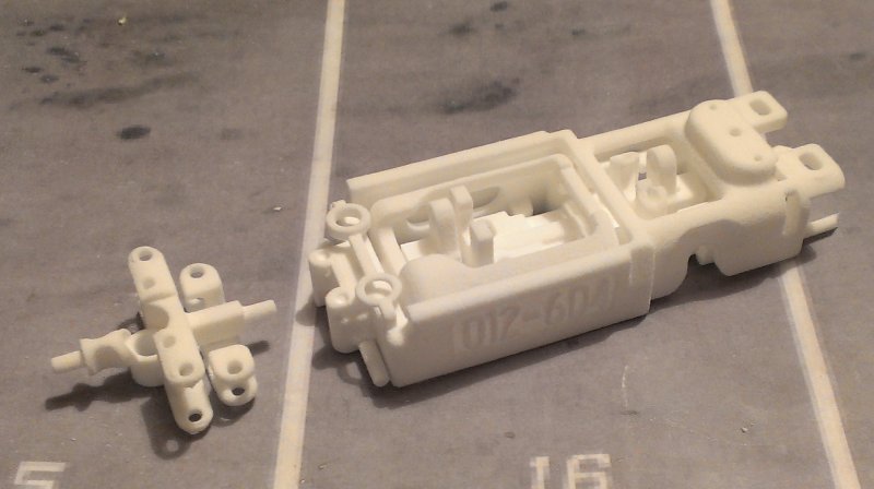
You can use a knife or cutters to separate the components by cutting where shown.
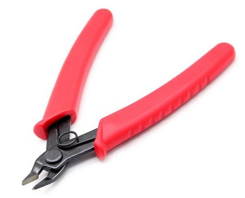
Everyone knows what side cutters look like, see below
But my life was transformed when I found flush side cutters, the jaws look like this, ground flat.
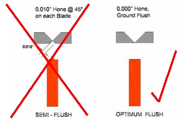
They allow you to snip very close to what you’re cutting and saves a lot of work with a scalpel and files later on.
First, remove the Guide Spacers, the two circles on their frame.
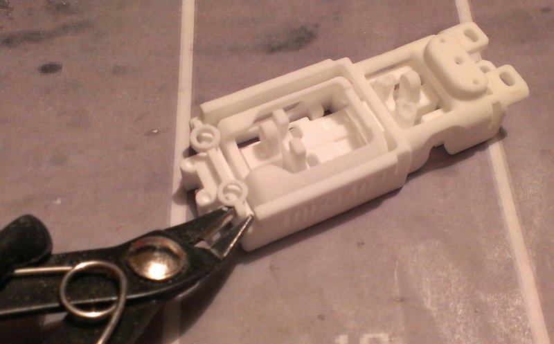
With the Bridge removed you can cut out the Front Hubs
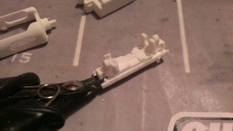
With the hubs removed, cut the 2 square supports off.
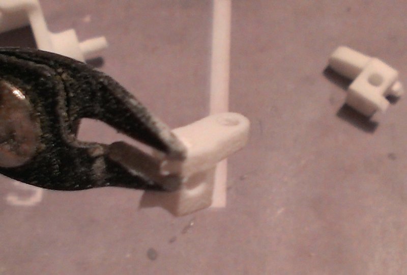
Cut off the support squares from the Chassis Front
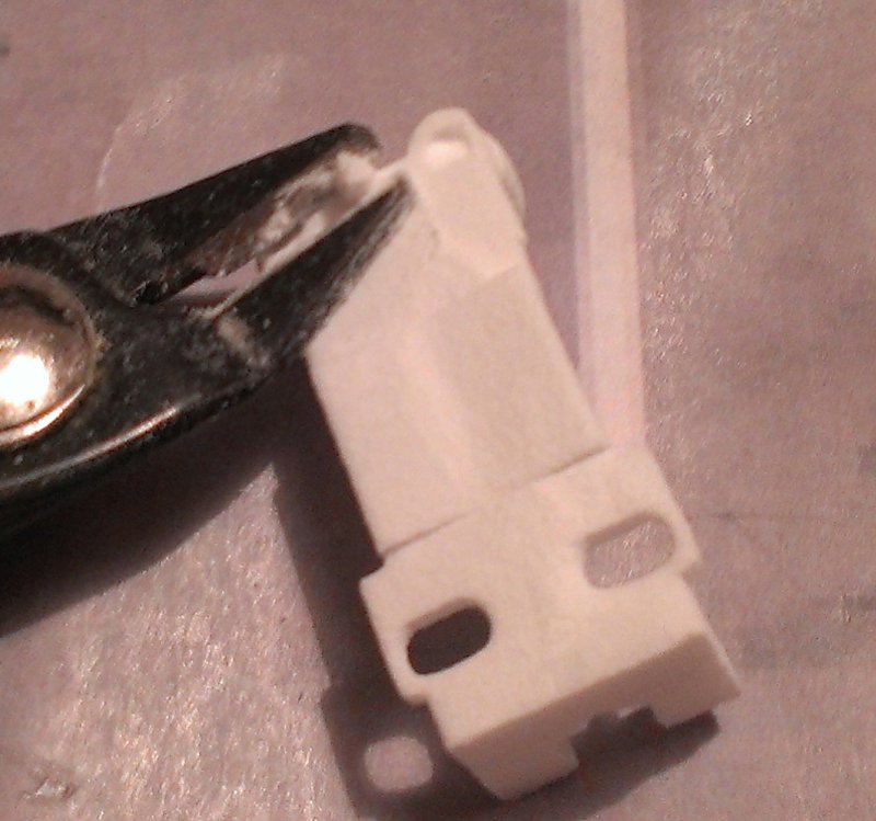
With everything apart it should look like this
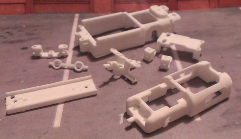
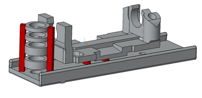
Some chassis are packaged slightly differently, they have 4 round spacers on top of each other. If you have one of these, you need to cut the red parts as shown below. First remove the front hubs.


Next, remove the Bridge that adjusts the wheelbase, and the motor pod.


Once the parts are free you can separate the Front Chassis (2 short cylinders to cut) and the spacers
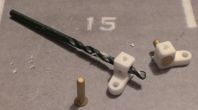
Take the Left & Right Front Hubs and run the 2.4mm drill through the holes as shown. Push the stub axles through, note the orientation! The stub axle should push out so the wheel rides against the flat surface and the head of the stub axle fits in a recess.
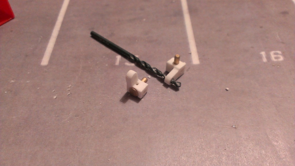
Now run the 2.5mm drill bit through the other holes as shown.
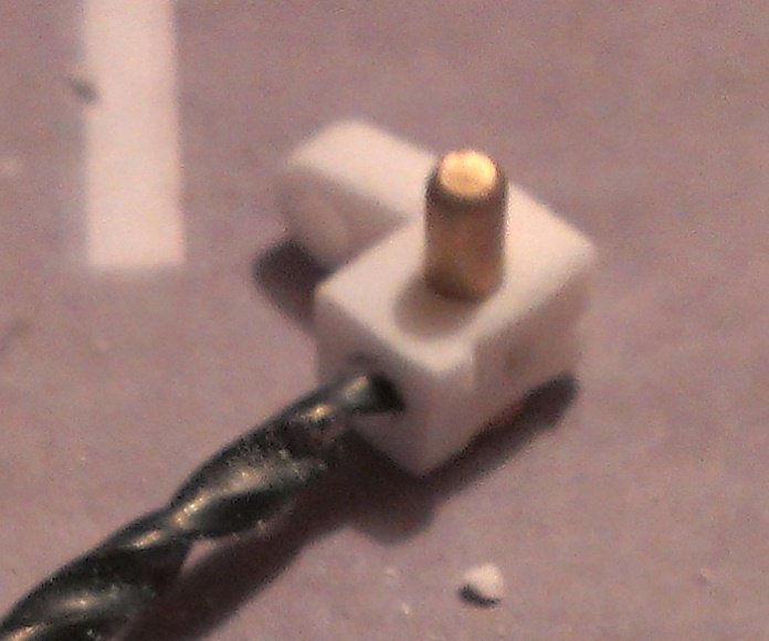
Finally, use the 2.4mm drill bit to clear out the Nylon powder from the upper and lower holes. Don’t go all the way through, only about 2mm deep!
Now take the Front Axle (this is the 27mm one, others are wider but work the same) and push the 4mm long pins in 4 places.
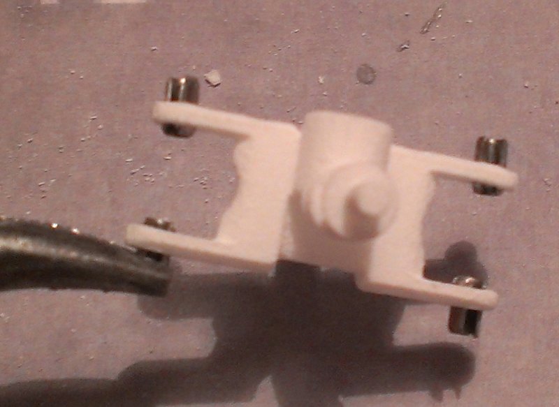
Put all the parts the right way around as shown.
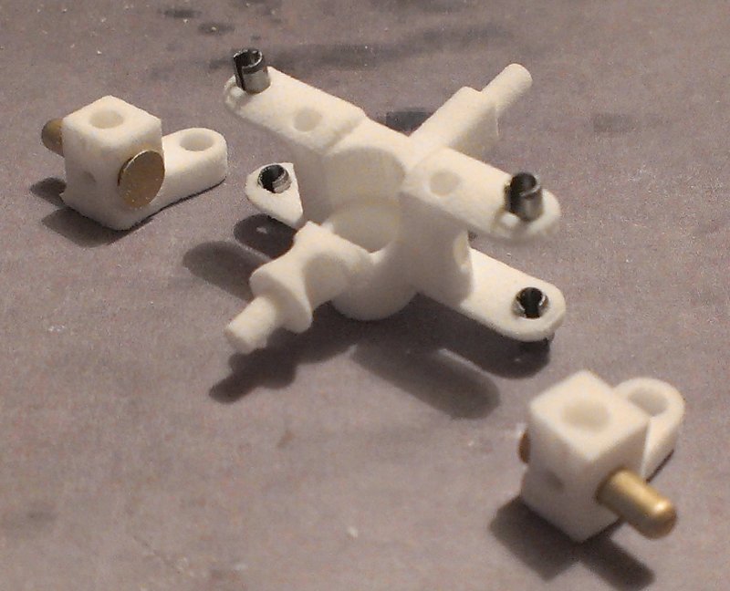
Using a pliers, gently squeeze the pins into place.
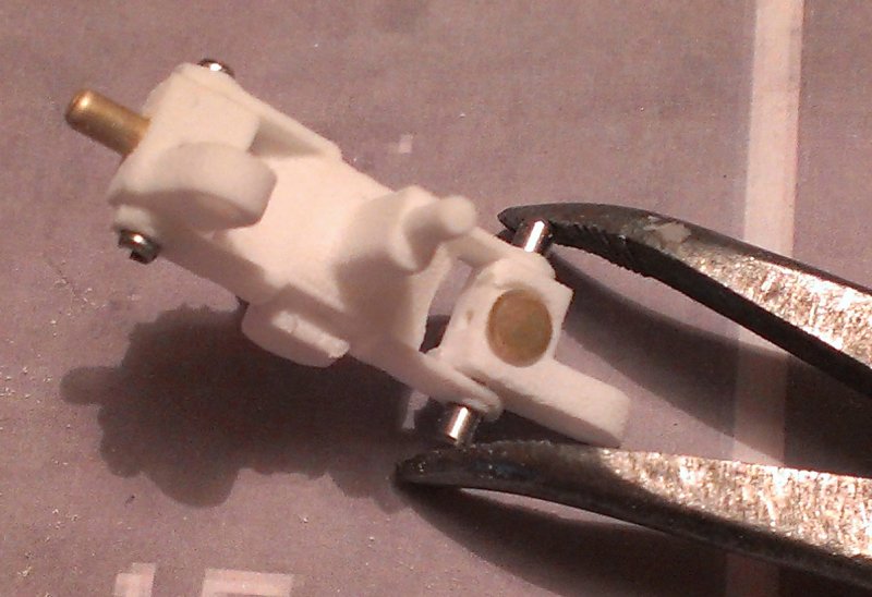
Make sure the Hubs rotate smoothly in the Front Axle. There should be no drag or graunching as it steers.
Now take the Steering Link and the longer pins, and push them in as shown.
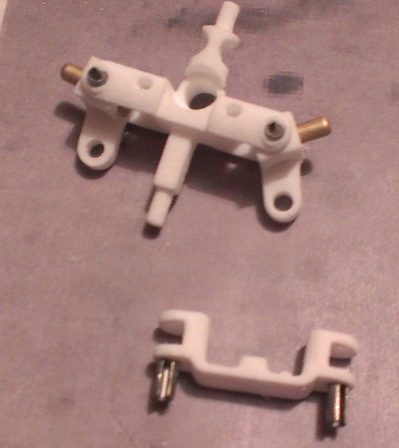
Check the orientation of the Steering Link with the arrow pointing forwards.
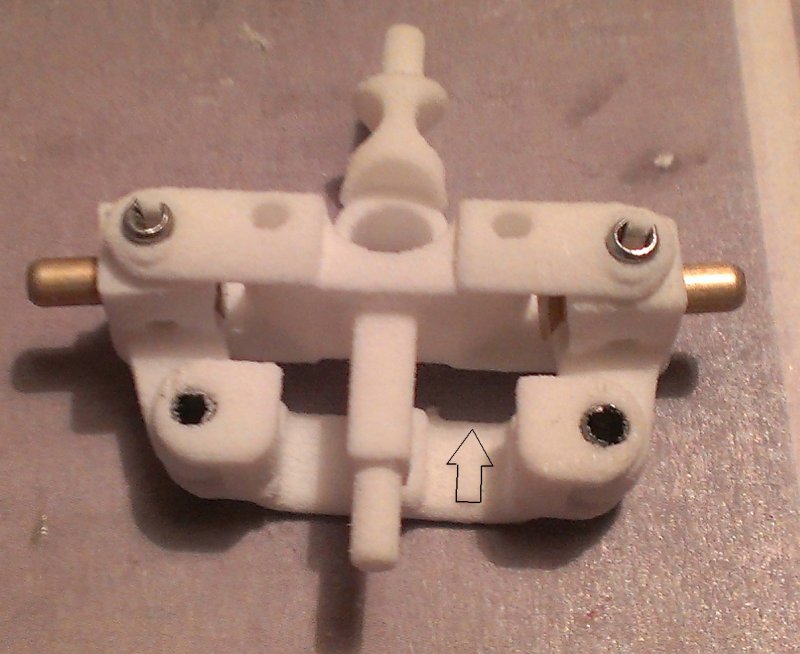
Then using a pliers, gently push the pins through.
Again, check there’s no drag when the steering is operated. Sometimes it helps to give the Steering Linkage a wiggle up and down to make sure everything is in clearance – especially if you’ve been too strong squeezing the pliers!
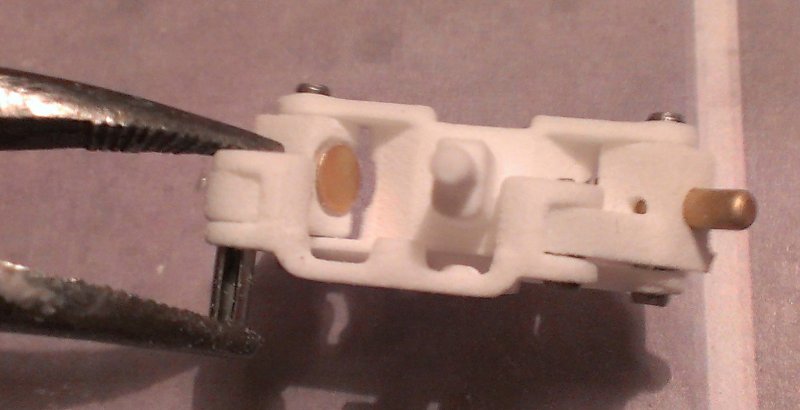
Now take the long 2mm grubscrews and insert them all the way through the holes as shown. They should go upwards.
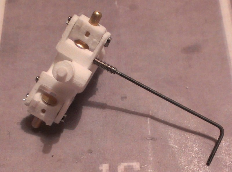
And when finished they should just show through the top of the hole.
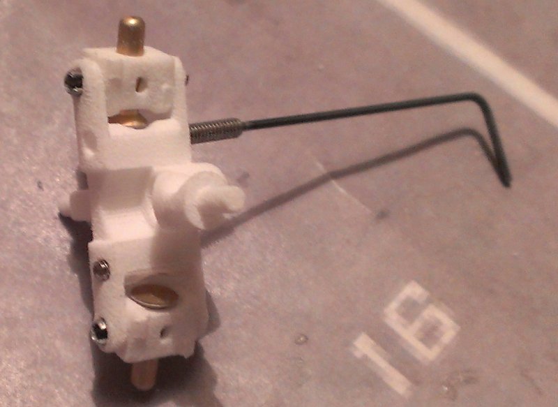
Take 2 of the plastic bearings and push them onto the Front Axle as shown.
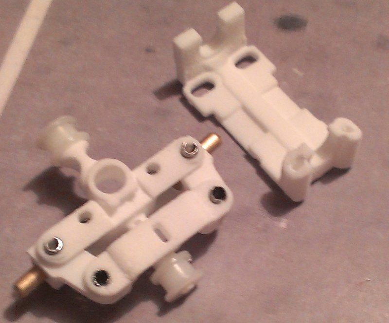
Then supporting with your fingers, clip the Front Axle into place. Make sure it’s the right way around!
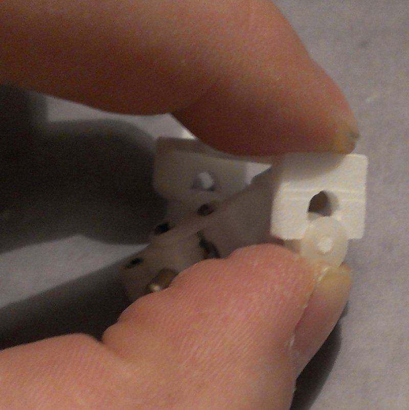
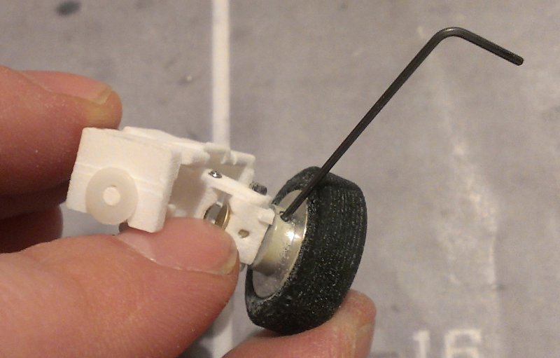
Slide the wheels onto the Stub Axles and you’re done for the front end!
Here we go for the rear, this is a bit quicker. Take the Motor Pod and insert the Spring Adjusters. The ones shown have a washer, later ones have a nut glued on. Push the hex key though up the hole, put the Spring Adjuster on it and wind it downwards. It starts off like the one on the left and when installed it should look like the one on the right.
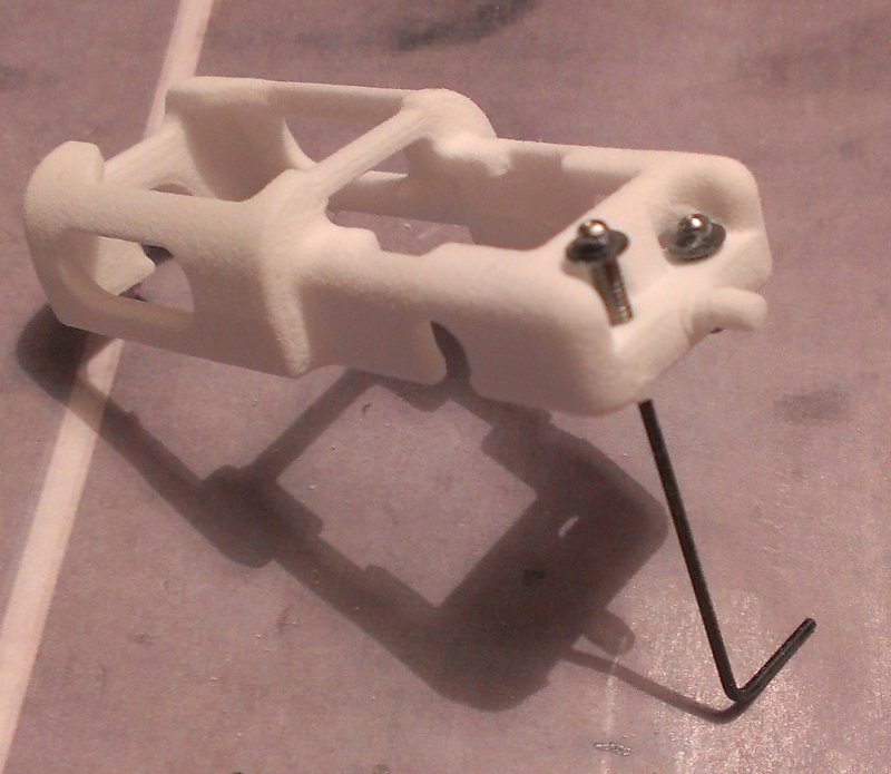
Turn the Motor Pod over and check there are no tiny bits of flash left where the motor will fit.
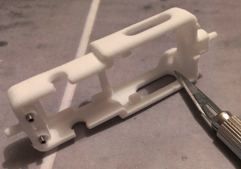
Push the rear of the motor in as shown, it should hook onto the lugs on the Motor Pod.
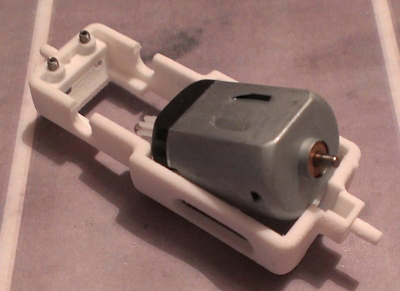
Gently clip in the front of the motor.
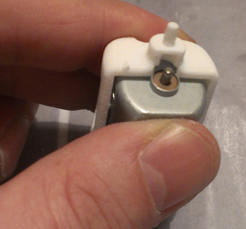
It should look like this.
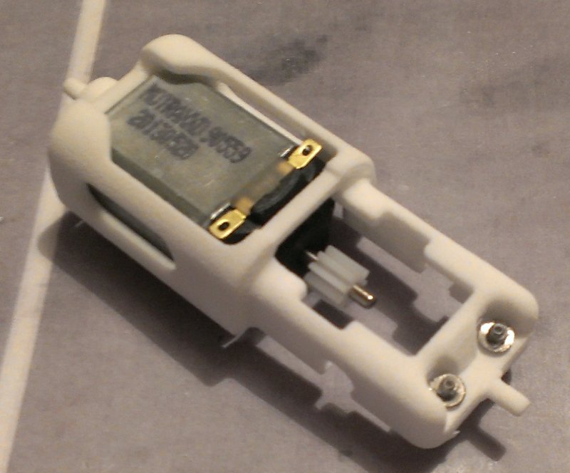
Now we can fit the rear axle. Supporting with your fingers, push the axle into place on its bearings.
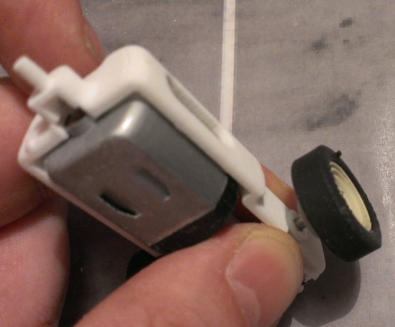
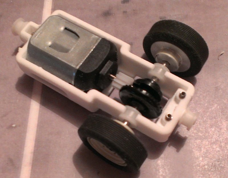
Finally, put the plastic bearings on both ends of the Motor Pod and move onto the Rear Chassis.
As I’ll be building this chassis for the VW Beetle, I need to cut off 2 of the rear body mounts. If you’re using any other bodyshell you can skip these next few photos. Only cut if you’re building for the 1963 Volkswagen, the 1967 Baja Bug or the 1976 Lotus. For all the other cars, the back of your chassis should look like this.
You’re making one of the VWs or the Lotus? Let’s cut off the 2 rear fixings!
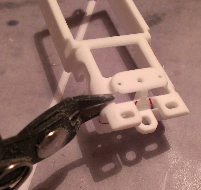
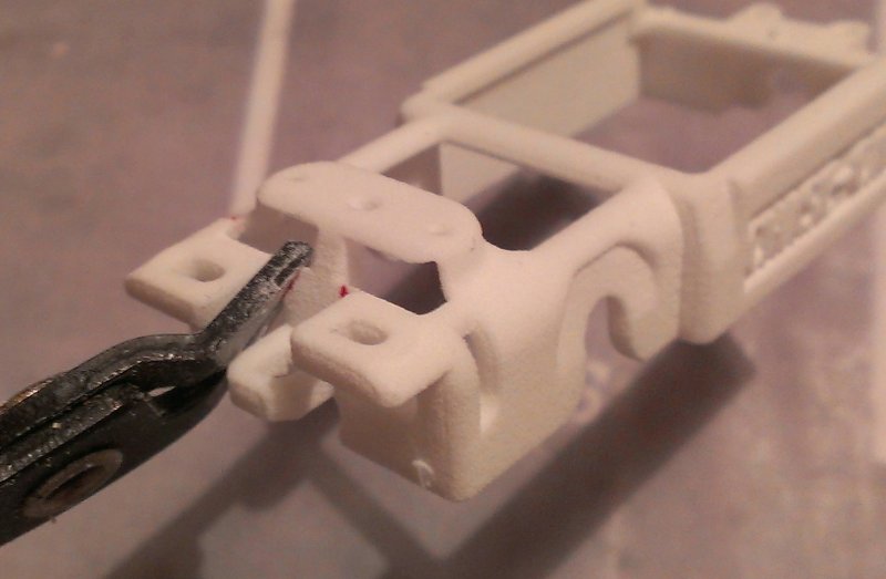
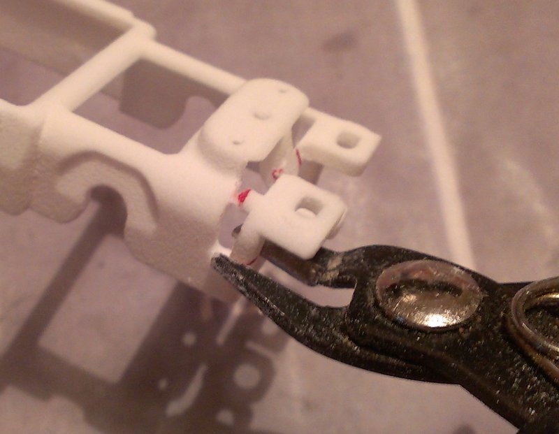
Both upper body mounts need to come off, make 3 cuts on each side where this is marked in red.
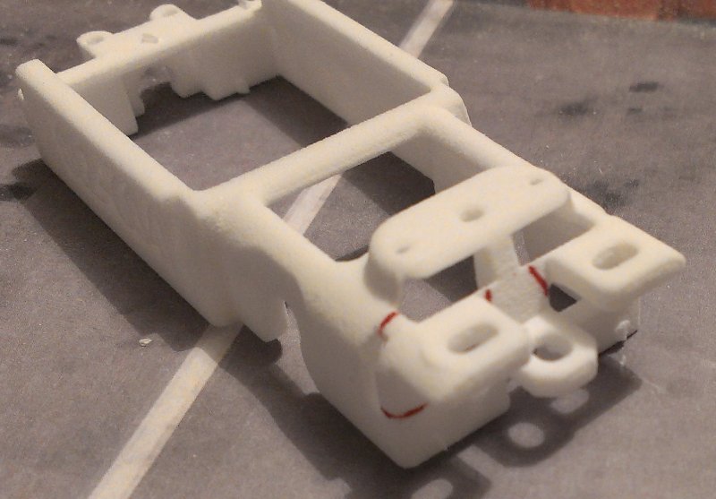
First cut vertically.
Now cut diagonally.
Finally, cut horizontally.
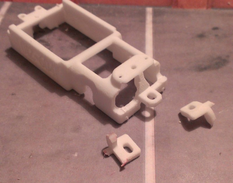
Do this for each side and it should look like this.
If you’re building anything except the VW Beetle and the Lotus, you can join us again. Welcome back.
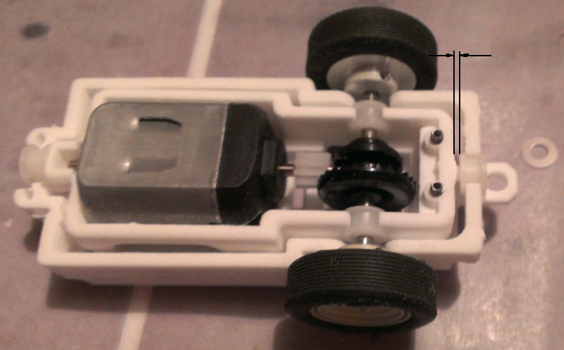
Lay the Motor Pod into the Rear Chassis and check for any gap as shown. You need a small working clearance for it to pivot, but if the gap is too large fit the plastic washer here.
Using your fingers to support, click the Motor Pod into place.
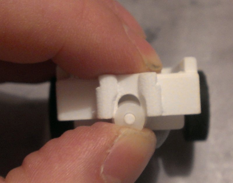
When assembled it should look like this and rotate freely.
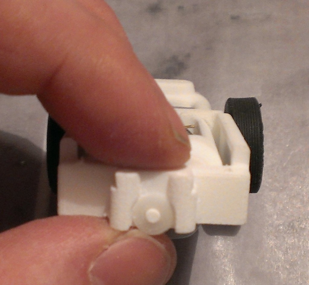
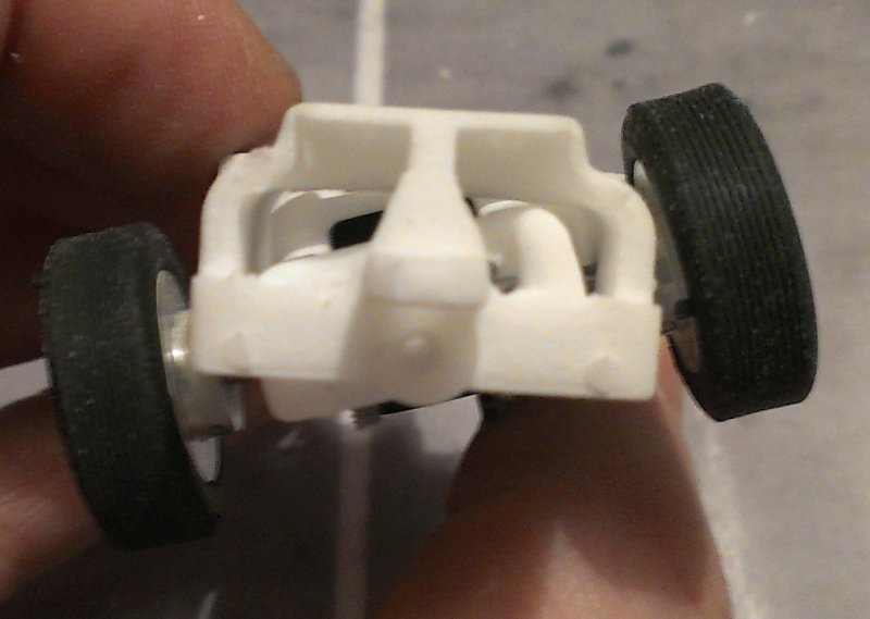
Check it moves through the full travel with no friction.
Now take the springs and hook them into place. I use a screwdriver to hold them. First, put one end of the spring onto the Spring adjuster.
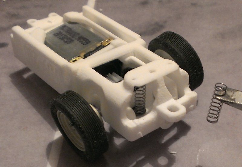
And then push the top end of the spring onto the small lug on the Rear Chassis.
They should sit level like this. If the Motor Pod isn’t quite level in the Rear Chassis, turn the Spring Adjusters so that when you move either wheel it always returns back to centre.
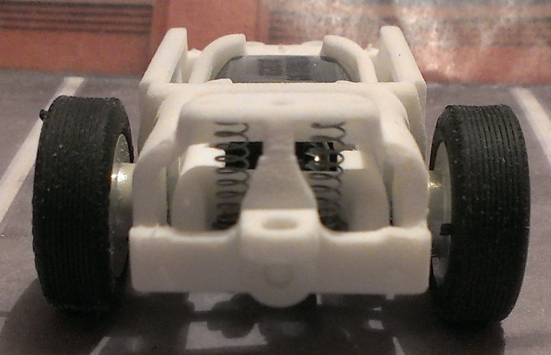
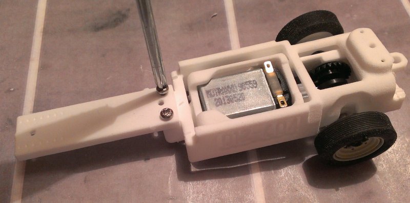
Take the Bridge part, that’s the one that joins the Front Chassis to the Rear Chassis, and screw it to the Rear Chassis.
Line up the wheels with the bodyshell you’re going to use to see how much needs to be trimmed from the Bridge. Make a mark a few mm forwards of the Front Chassis screw holes.
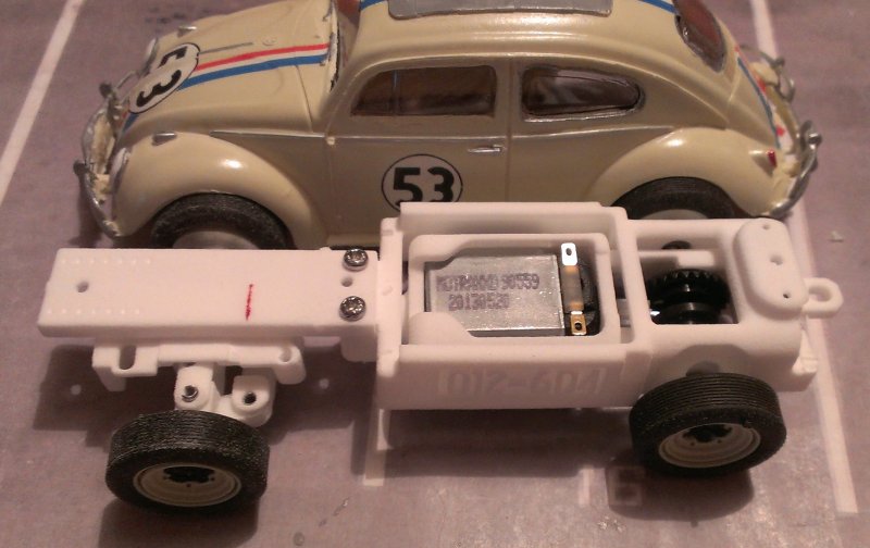
Cut the Bridge to length.
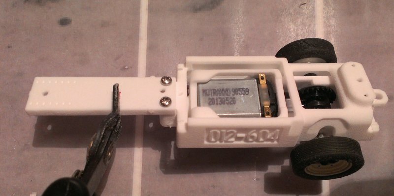
Put the Front Chassis in place to check where the holes need to be drilled.
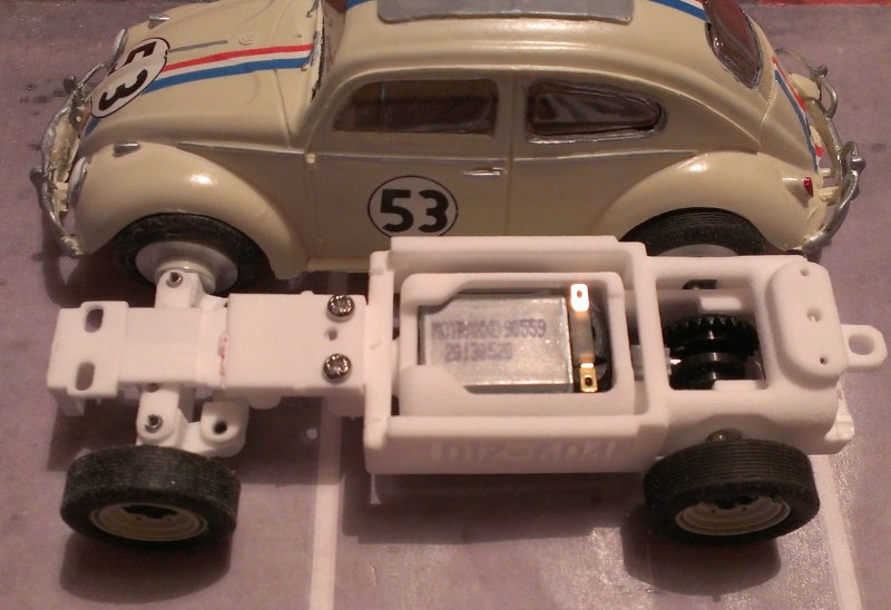
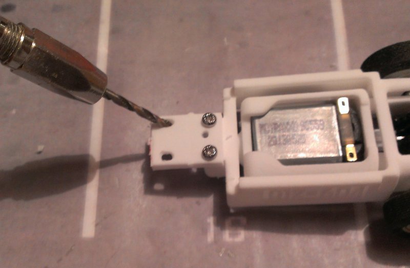
Now drill 1mm pilot holes in line with the existing screw holes.
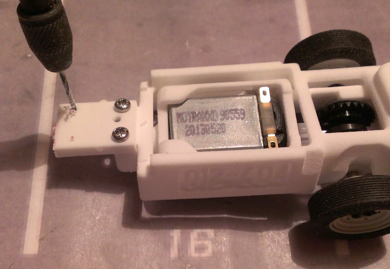
With the 2.4mm drill, open up the holes.
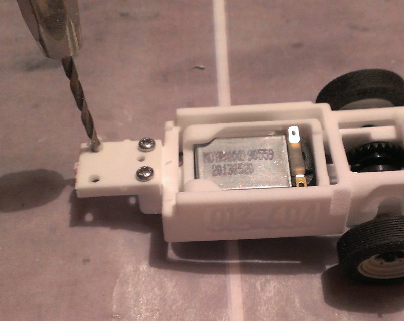
You can elongate the holes easily to give you some fine adjustment.
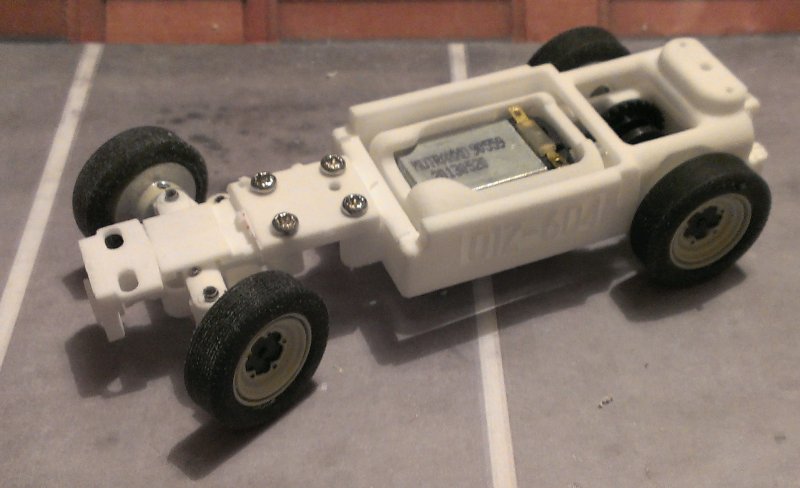
Put the 2 last screws in place.
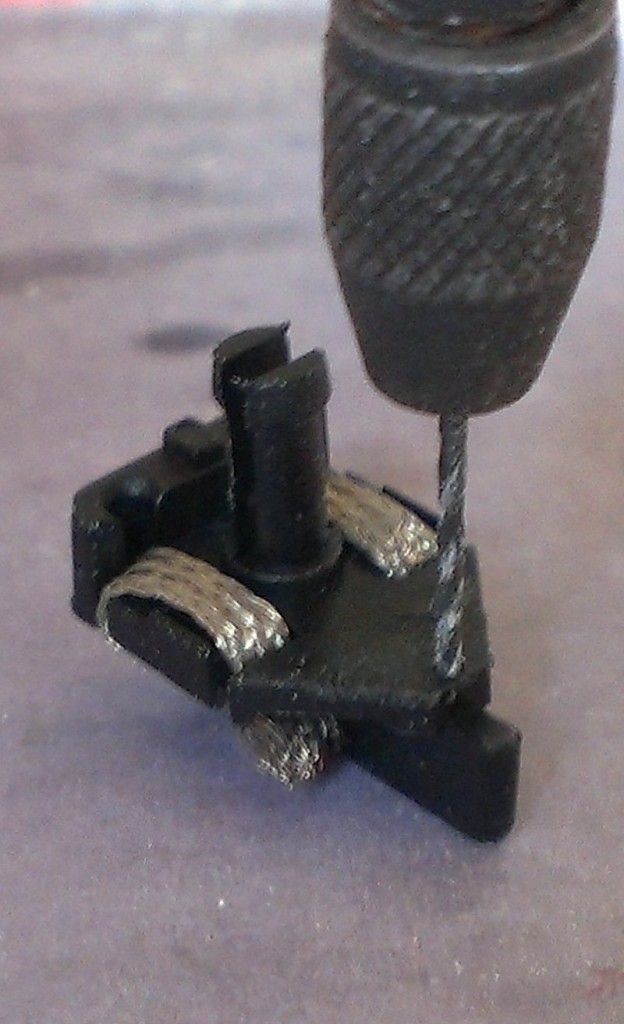
Now for the guide. You need to drill a 1mm hole as shown.
Add a tiny blob of superglue over the hole.
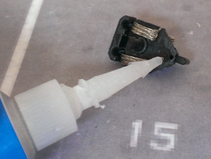
Then push in the 1mm brass bar.
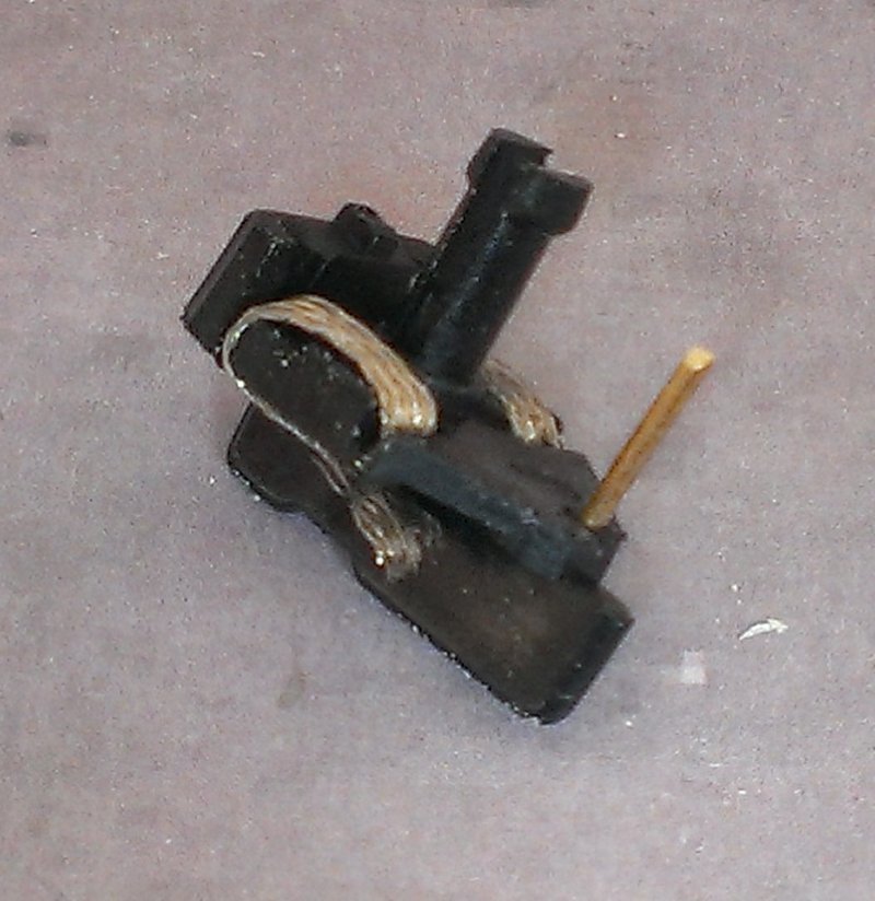
Push it into the Front Axle and check to see how much sticks through the Steering Linkage.
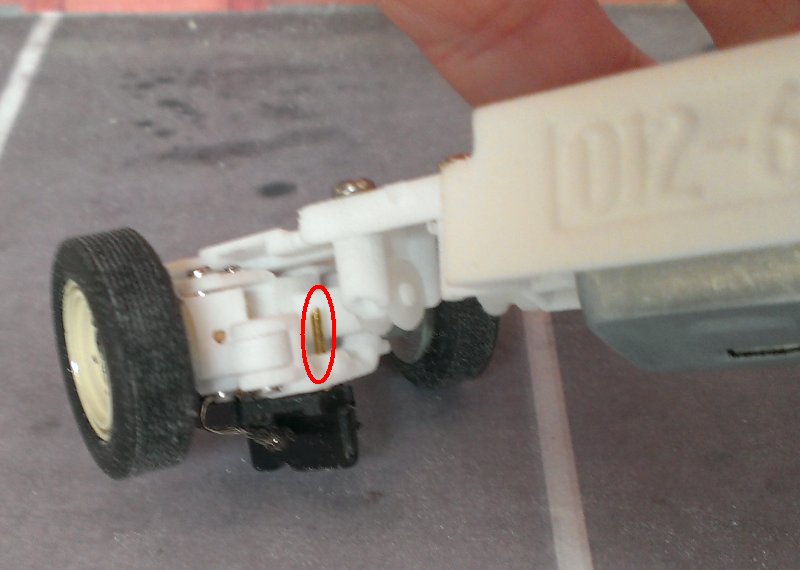
Cut the 1mm brass bar shorter so it just shows through the Steering Linkage.
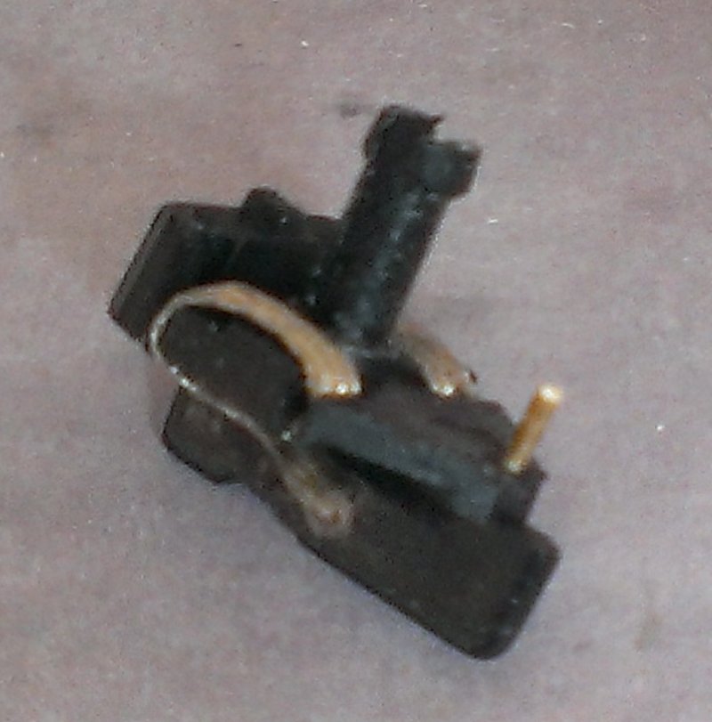
Like this.
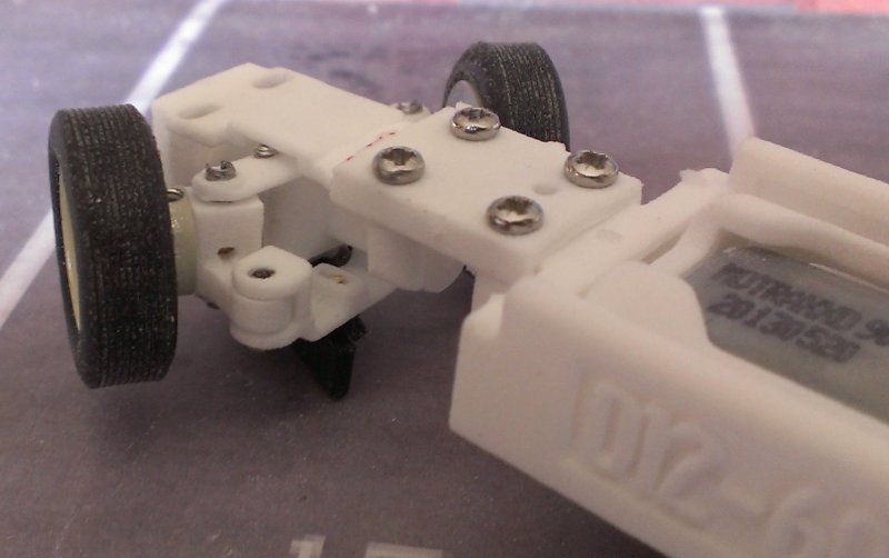
Now trim the insulation from the wires and pass through the ferrules and back about half way.
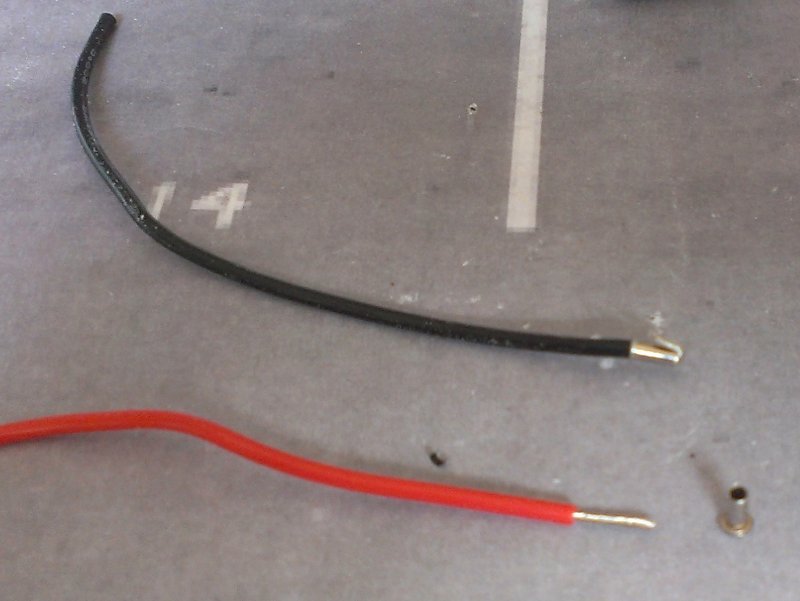
Push the ferrules into the guide.
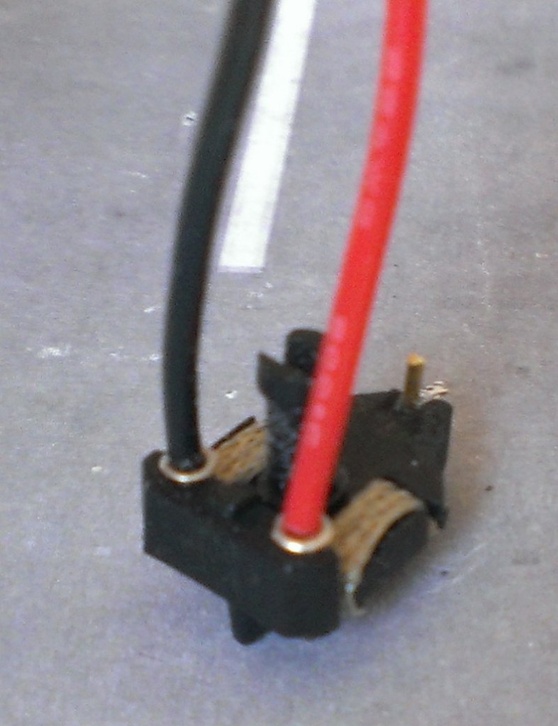
Cut the wires to length, allow for steering and suspension movement but keep them quite short.
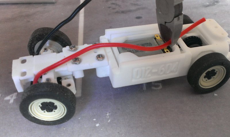
Solder the wires onto the motor and use the cable tie to hold them in place. The reason for this is that the interior is sometimes a close fit on the chassis and when the Motor Pod rotates the wires can hit the underside of the interior, jamming it.
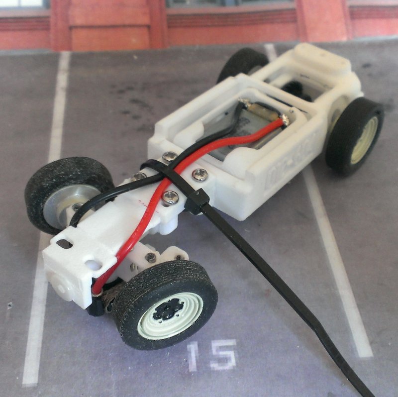
Before pulling the cable tie too tight, make sure there is enough slack between cable tie and motor to allow the Motor Pod to rotate freely and spring back to centre.
And we’re done! Have a look at chassis setup and how to drive next.
Once you’re happy with the performance, put a tiny drop of superglue on the linkages to stop them coming loose.
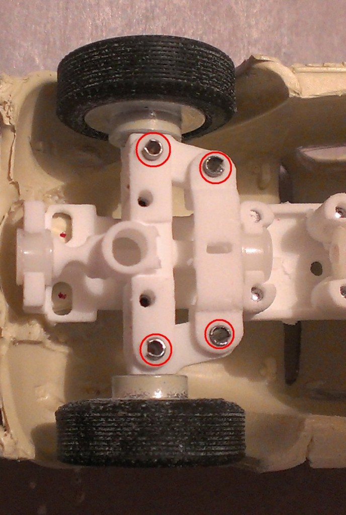
And on top here.
